Free CXC Technical Drawing Paper 2 May/June 2018 past paper from 2018. Includes a worked answer key. Open the PDF, take a timed test, and study with AI on Caribbean AI.
Answer keys are free on Caribbean AI. View the answers to every past-paper question at no cost - no payment needed - with step-by-step worked solutions and instant AI marking available on Premium.
CSEC Technical Drawing Paper 2 May/June 2018 - Free CXC Past Paper with Answers
Free CXC Technical Drawing Paper 2 May/June 2018 past paper from 2018. Includes a worked answer key. Open the PDF, take a timed test, and study with AI on Caribbean AI.
Opening the interactive papers…
Every question from this paper as text. See the answers and worked solutions. Questions are the property of the Caribbean Examinations Council; Caribbean AI is not affiliated with CXC.
Figure 1 on the enclosed sheet, shows the third angle orthographic projection details of the parts that make up a pipe vice assembly. In assembly, the screw, part (3), is inserted into the base part (1) from above. The moveable jaw part (2) is then attached to the screw from below. The handle part (4) passes through the hole in the screw and is secured by the handle ends, part (5), on either end.
(a) Draw, FULL SIZE, in either, first angle or third angle orthographic projection, the following views of the assembly: (i) A plan of the assembled parts. Show all hidden details. (ii) A full sectional front elevation on cutting plane 'X-X'.
(b) Show SIX main dimensions to include a length, a diameter, a radius and a metric screw thread specification.
(c) Print the title, "Pipe Vice Assembly", and the scale used. Indicate the projection method used by symbol.
NOTE: All fillet radii are 5 mm.
[90 marks]
Draw, FULL SIZE, in either, first angle or third angle orthographic projection, the following views of the assembly: (i) A plan of the assembled parts. Show all hidden details. (ii) A full sectional front elevation on cutting plane 'X-X'.
A plan of the assembled parts. Show all hidden details.
A full sectional front elevation on cutting plane 'X-X'.
Show SIX main dimensions to include a length, a diameter, a radius and a metric screw thread specification.
Print the title, "Pipe Vice Assembly", and the scale used. Indicate the projection method used by symbol.
Make single freehand proportional orthographic sketches to illustrate the specified sectional views of the mechanical objects given.
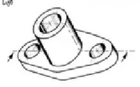
(a) Figure 2 (a) shows a pictorial view of a mechanical part. Use a single orthographic freehand sketch to illustrate a (i) full sectional view of the mechanical part (ii) half sectional view.
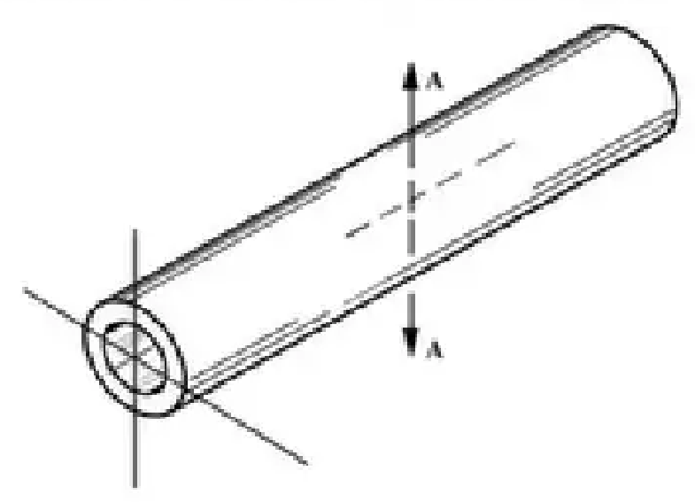
(b) Figure 2 (b) shows a pictorial view of a cylindrical metal pipe. Make a single orthographic proportional sketch to illustrate a (i) revolved sectional view on the cutting plane line A-A (ii) part sectional view of the pipe.
[30 marks]
Figure 2 (a) shows a pictorial view of a mechanical part. Use a single orthographic freehand sketch to illustrate a (i) full sectional view of the mechanical part (ii) half sectional view.
full sectional view of the mechanical part
half sectional view.
Figure 2 (b) shows a pictorial view of a cylindrical metal pipe. Make a single orthographic proportional sketch to illustrate a (i) revolved sectional view on the cutting plane line A-A (ii) part sectional view of the pipe.
revolved sectional view on the cutting plane line A-A
part sectional view of the pipe.